1. Introduction
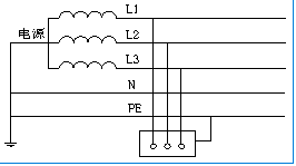
There are three basic types of low voltage power distribution grounding and zeroing systems: IT, TT, and TN. TN is divided into three derived types: TN-C, TN-S, and TN-C-S.
The first letter indicates the state of the power supply neutral point with respect to ground:
T—indicates that the neutral line of the power supply is directly grounded; I —indicates that the neutral line of the power supply is not grounded or is grounded with high impedance.
The second letter indicates the state of the load side relative to ground:
T — The externally leaking conductive parts of the electrical device are directly grounded, and the grounding point is independent of the grounding point at the power supply end;
N — The exposed conductive parts of the electrical device have a direct electrical connection to the grounding point of the power supply terminal.
The third letter C- indicates that the neutral line (N line) and the protective zero line (PE line) are shared; the fourth letter S- indicates that the neutral line (N line) and the PE line are separated.
1.1 IT System
Definition: The power supply is not grounded, and the equipment housing is grounded.
Protection: The insulation resistance of the monitoring system to ground.
.jpg)
1.2 TT System
Definition: Power supply grounding, equipment housing grounding.
Protection: Monitoring system residual current to ground.
.jpg)
1.3 TN-C System
Definition: Power supply and equipment housing grounding. Two grounds connected and neutral ground separated.
Protection: Monitoring system residual current to ground.

1.4 TN-S System
Definition: Power supply grounding, equipment housing grounding. Two grounds connected, zero ground combined.
Protection: Monitoring system residual current to ground.

2. Comparison between IT system and TN system
2.1 TN system: Poor power supply safety and continuity
In a grounding system, when a live wire grounding fault occurs, the neutral live wire is short-circuited to the ground, and the circuit breaker trips, affecting the continuity of power supply.
Any electrical equipment powered by the TN system will have a certain amount of leakage, which will pose a threat to medical staff and patients.
If the leakage current of the equipment is too large and exceeds the operating current of the leakage current protection circuit breaker, the circuit breaker will trip, which will also affect the continuity of power supply.
.jpg)
2.2 IT system: Good power supply safety and continuity
The IT system is not grounded. When any live wire fails to ground (the first ground fault), the insulation monitor reports a ground fault, but the circuit breaker will not trip, and the system can continue to operate with the fault.
Because the system is not grounded, the leakage current forms a loop through the system distributed capacitance. Under high capacitance, the leakage current will be relatively small, and the normal system leakage current is below mA.
For medical IT systems, the IEC standard requires that the input and output circuit breakers of the IT system are not allowed to have overload protection functions, and the overload will not be cut off.
.jpg)
3. Solution

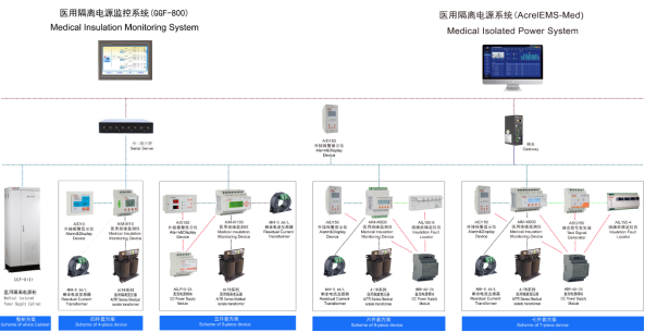
Medical IT System Insulation Monitoring Products
Name and Model | Product Picture | Description |
| AITR series isolation transformer is specially used in medical IT system. The windings are treated with double insulation and have electrostatic shielding layer, which reduces electromagnetic interference between windings. The PT100 temperature sensor is installed in the wire bag to monitor the temperature of transformer. The whole body is treated with vacuum invasion paint,which increases mechanical strength and corrosion resistance. The product has good temperature rise performance and very low noise. | |
| AIM-M200 medical intelligent insulation monitoring instrument adopts advanced micro-controller technology,which has high integration, compact size, convenient installation and integrates intelligence, digitization and networking in one. It is ideal selection for insulation monitoring of isolation power system in Class 2 medical locations such as operating room and intensive care unit. | |
| The AKH-0.66P26 type current transformer is the protective current transformer supporting the AIM-M200 insulation monitor, of which the maximum measurable current is 60A and the transformation ratio is 2000:1. The current transformer is directly fixed inside cabinet by screwing, and the secondary side is leaded out by the terminal, which is convenient to install and use. | |
HDR-60-24 direct-current power supply can provide 24V DC power supply simultaneously for AIM-M200 medical intelligent insulation monitoring instrument, ASG150 test signal generator, AIL150 series insulation fault locator and AID150 centralized alarm and display instrument. The power supply is of high capacity, stable voltage output and convenient installation, which can meet the power-supply requirements of the above-mentioned meters and is the recommended power supply product. | ||
| AID150 centralized alarm and display instrument adopts the LCD liquid crystal display and achieves data exchange with AIM-M200 medical intelligent insulation monitoring instrument through RS485 communication interface, which can real-time monitor multi-channel data of AIM-M200 medical intelligent insulation monitoring instrument. | |
The ASG150 test signal generator adopts 32-bit microprocessor chip and high-precision signal generation circuit to realize the generation of specific test signal. When the monitored IT system has insulation faults, it can start up and produce test signal in time, working with the insulation fault locator to realize insulation fault location. | ||
| AIL150-4/AIL150-8 insulation fault locator adopts high sensitivity transformer combined with high precision signal detecting circuit, which detects the signal imported into the system from ASG150 test signal generator and accurately locates the circuits which have insulation faults. AIL150-4 insulation fault locator can locate the insulation faults of 4 circuits, and the AIL150-8 insulation fault locator can locate the insulation faults of 8 circuits. |