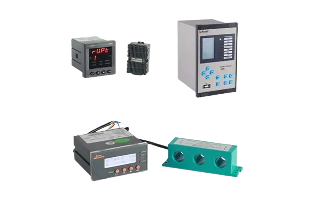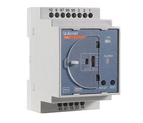

1) How to deal with the insulation fault reported by the insulation monitor?
Insulation monitoring reports an insulation fault. It may be that one of the two lines of the IT system on the secondary side of the isolation transformer has a ground fault,which can be restored to normal after removal.If the circuit on the secondary side of the isolation transformer is normal, check whether the two terminals of the insulation monitor connected to the IT system are connected to the primary side of the isolation transformer. If so, adjust it to the secondary side of the isolation transformer.
2) If the insulation monitor reports an overload fault and an over-temperature fault at the same time, how to deal with it?
This kind of fault occurs probably because a wire on the secondary side of the current transformer is grounded. Disconnect it from the ground wire, and then the instrument can return to normal. It is particularly emphasized here that the secondary side of the AKH-0.66P26 current transformer matched with the insulation monitor cannot be grounded when in use.
3) If the input terminal of the isolation transformer has power while the output terminal has no power, how to deal with it?
Check whether the wires leading out from the wire packs to the terminal at the output end of the isolation transformer are loose at the terminal. The above problems are usually caused by looseness here. Use an electric screwdriver to re-tighten and compact the wiring, and the output voltage will return to normal.
4) If the resistance between the two ST terminals of the isolation transformer is infinite, and the meter reports an over-temperature fault, what should I do?
Check whether the two wires drawn from the inside of the transformer wire packs and connected to the ST terminal are loose or disconnected at the terminal. If the wires are loose, re-tighten and compact the wires to return to normal. If there is no abnormality in the wiring, contact the after-sales personnel to communicate and deal with it.
5) If AID150 is connected to 5 sets of AIM-M100, why does AID150 alarm only after the first insulation monitor alarms? How to deal with it?
This is because the "number of access systems" in the AID150 instrument has not been set. Press the menu key of the instrument, enter the password 0000 and press OK to enter the menu, then set the parameter of "number of access systems" to 5, press self-test to return and confirm to save. The above problems can be solved.
6) What should be paid attention to when insulation monitoring and fault location products are connected to CAN bus?
The CAN bus wiring should also be connected hand in hand. Besides, the first and last ends of the CAN bus need to be connected in parallel with 120Ω matched resistance to ensure the reliability of communication. Both of the AIL150/AIL160 insulation fault locator have two sets of DIP switches for switching matched resistance. Install the AIL150/AIL160 at the beginning or end of the bus, and you can set all the DIP switches to the 1 position, so that the matched resistance will be connected.
7) If the fault location product does not respond and cannot locate the fault when an insulation fault occurs, how to deal with it?
① First check whether the CAN communication wiring is normal and whether the matched resistance has been connected;
②Enter the menu of the insulation monitor and check whether the Locat setting in the communication setting is Yes. If it is No, change it to Yes. Then press the self-test key to return to save.
③Enter the menu of the insulation monitor again, set the CAN address, change the original 1 to 2, and then return to save. At the moment of confirming to save, check whether the communication indicators of ASG150 and AIL150/AIL160 are blinking. If the communication indicators are blinking at the moment of saving the address , it indicates that the address setting is normal and the communication is normal.Then the locating function can be started normally for locating.
8) When the insulation fault locator is threading the wire, should the loop thread through one or two wires? Is there a direction for threading?
The two wires of the single phase must pass through the transformer before connecting to the load. There is no requirement for the direction of the wires.But considering the convenience of wiring, it is recommended to thread the wires uniformly from top to bottom.
 English
 日本語
日本語 한국어
한국어 français
 Deutsch
 Español
 italiano
 русский
 português
 tiếng việt
 Türkçe
 العربية


